Gyrobob
Serious Thumper
 Offline

Posers ain't motorcyclists
Posts: 2571
Newnan, GA
Gender: 
|
Part of the RYCA build process is to add 24 to the 5 wires that go from the ignition switch to the harness plug. There are lots of ways to do this:
1. Cut the wires somewhere, get five 2 lengths of wire, strip the 20 ends of wire, twist em together, wrap each twisted joint with electrical tape
2. Do #1 but use some twist-on household wiring connectors for each of the ten splices. (theres a lot of space under the RYCA seat, eh?)
3. Use crimp-on butt connectors
4. Solder the ten joints and wrap each with tape
5. Solder the ten joints and use heat shrink
6. Solder the ten joints, staggering the joints to minimize future electrical problems, use heat shrink
7. Find matching color and gauge wires, cut them to the new length, throw away the old wires, install new connectors on each end, in effect remanufacturing the entire bundle.
When I was a kid, I used #1, then actually used #2 on a Lambretta 150d I had in 1962.
#3 is acceptable for a RYCA, but doesnt end up very tidy looking, especially if you dont stagger the joints.
In the event the time, and/or tools, and/or resources are not available, I tend to prefer #6. See the pics below. Sorry for the fuzzy pics, but the normal camera wasnt available and I had to use a phone camera.
Also, my slim inventory of #14 and #18 wire didn't have matching colors, so I used what was available, and added some of my own markings.
I normally like crimp connectors, but I wanted the finished product, once wrapped in tape, to be a slim as possible.
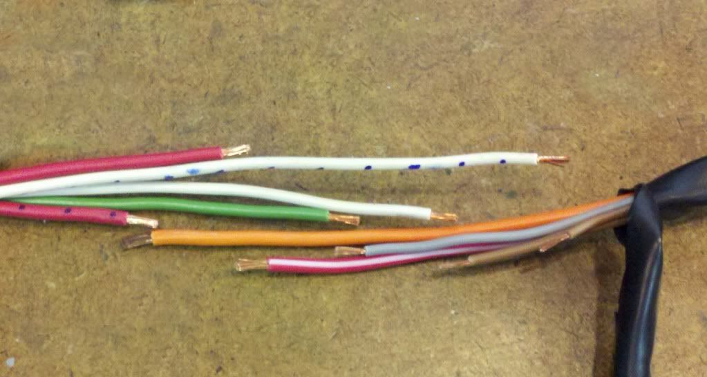
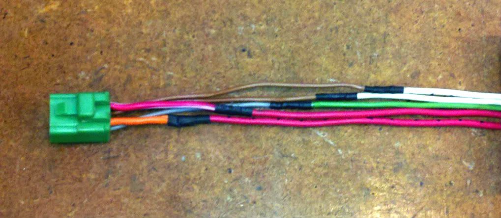
I like to stagger the splices in a bundle, for three reasons. 1. Appearance. 2. Fatigue resistance from having the splices spread out over the bundle 3. Electrical reliability from not allowing the splices to rub on each other,.. possibly creating a short. Here's a pic of the five wires from the switch,.. cut to mate with the five 24" wires.
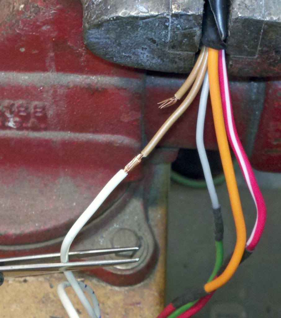
Here's a splice about to be soldered. Trim just a 1/4" from each wire, gently intermingle, then compact the joint with finger pressure, and make sure it is all held in place with no sideways strain on the joint or it will move when solder is applied, the wires heat up, and the insulation gets mushy.
Splice just soldered. Use the minimum amount of solder necessary to wet the entire joint. You'd rather not have solder traveling an inch on either side of the splice because it makes for a long fatigue-prone chunk of stiff wire. If you have any of the solder sticking out away from the joint, it is okay to trim it down as long as you don't get into the copper.
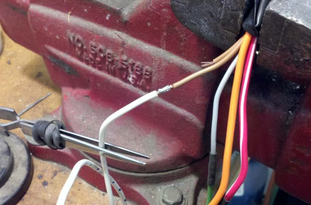
Then wrap one layer of electrical tape around the joint just wide enough to butt up on the insulation. The piece of e-tape needed will be about 1/4" by 3/8" just to fit one layer over the joint. This step is just to replace the layer of insulation stripped away from the ends of the wires earlier, and helps to smooth out the surface for the heat shrink in the next pic. The diameter of the joint should be about the same as the wire (with insulation) on each side of it.
Here is what the splices should look like, all staggered, spliced, soldered, and the individual joints heatshrunk. Again, sorry for the fuzzy pic.
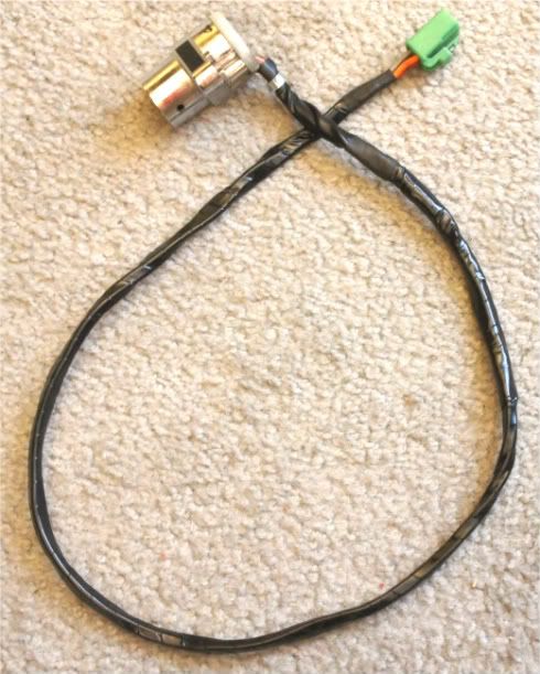
Heres the finished bundle, wrapped with e-tape, with larger heatshrink tubing over the ends of the e-tape to keep the ends secure.
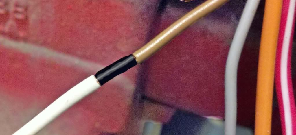
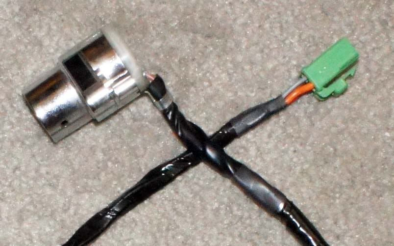
A closer pic of the heatshrink over the ends of the e-tape.
Doing it this way took two whole evenings; one for each bike in the Double RYCA build. Shheeeeeesh. It'll be worth it in the long run, though. I do so intensely hate trying to solve electrical problems.
|

 Pages: 1

