Donate!
Welcome, Guest. Please Login or Register :: View Members
Pages: 1
Send Topic Print
Suzuki wheel lacing (Read 361 times)
kernel ken
YaBB Newbies
*
Offline

SuzukiSavage.com
Rocks!

Posts: 34
Loveland Ohio
Gender: male
Suzuki wheel lacing
04/09/11 at 08:33:30
 
(NOTE This is part one of a two part series due to a max word limit for any posting.)


I wanted my Suzuki Savage wheels to be different that what you normally see on motorcycles. I was in the process of building a Ryca CS-1 café racer and decided to disassemble the wheels so I could polish the hub flanges and paint the center of the hub black. I also wanted the spokes black, so I painted them to.

I’ve laid out the steps I went through in the front wheel dis-assembly, reassembly and alignment. Before I get into the specifics of the process, there is some general information you should be aware of.

This wheel has 36 spokes comprised of two groups of 18 each. The difference between the two groups of 18 is where the bend occurs near the spoke head (the end that looks like a nail head). There is a longer bend in one set than in the other. The 36 spokes are arranged in a repeating pattern of 4 spokes, occurring 9 times to complete the wheel. You’ll see the difference between the spokes and where they’re located in photo’s a little later.

Next we’ll look at the wheel rim. The holes or dimples in the rim are at 4 different angles. These angles match up with the 4 spoke pattern referenced above. You’ll see the pattern and how the spokes are aligned in them in the photos.

The last part to check on before dis-assembly is the hub. Note that the holes in the hub flanges are off-set from one another. The holes located near the outside edge of the flange have the spokes with the short bend in them. The holes located further back from the edge of the flange have the spokes with the longer bend in them.

Since I was starting with an assembled wheel, I took quite a few close-up pictures of the spoke patterns, where they were at on the flange and where they attached to the rim. If you don’t have access to a camera, make detailed sketches. I knew I’d have the wheel apart for some time and didn’t want to forget exactly how things should fit together. I’ve included photos with this post but I suggest you take your own also. Better to have too much information than not enough to finish the job.

Okay, let’s get started…


(ASSEMBLED WHEEL)
Step 1 Tire & Disk Brake Removal
In this first photo, look at the valve stem at the bottom of the tire. As you look to the right of the valve stem the first 4 spokes show the pattern that is repeated 9 times around the wheel.

Besides having to removing the tire, I also removed the disk brake rotor. It makes it easier to remove and re-install the spokes by doing that.


Step 2 WD40 the Nipples
The wheel had been assembled and on the bike for quite awhile. Because of that it was difficult to loosen the nipples from the spokes. I applied a generous helping of WD40 to both the spoke side of the nipples and the end of the nipple in the rim. Give the oil about 15 minutes to do its job. (I used WD40 because that’s what I had on my work bench. Any penetrating oil will probably do the job.)
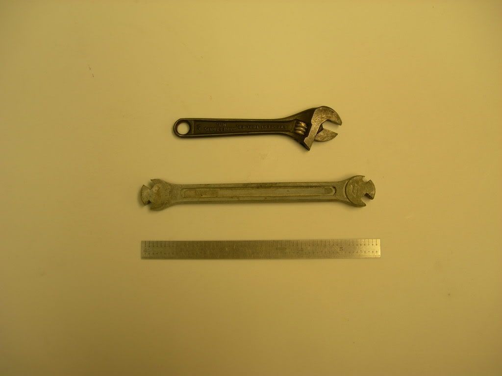


(PHOTO OF TOOLS)
Step 3 Gather the Needed Tools
There are some “have to have” tools and some “handy to have” tools. You have to have either a spoke wrench or a small adjustable wrench. If you use an adjustable wrench, be sure to tighten it each time you apply it to the nipples. The nipples are a soft material and will round off easily.

You’re also going to need a dial indicator that reads in .001 inch increments with at least .250 inch total travel. The one I used has a 1 inch travel. An indicator stand is also needed to hold the indicator in the proper location for the measurements. (Both items can be purchased from Harbor Freight for about $50 total.

I found that a 6 inch scale was handy to have. I used it to check for dents or slightly bent places on the rim.

Tools that are handy to have around, but hope you don’t have to actually use, are vise grips and a large flat blade screw driver.

If you round off the nipple, you can try to remove it with a large flat blade screw driver applied to nipple end inside the wheel rim. If that doesn’t work try vise grips. The last option is to cut the spoke to remove it. Obviously, you want to avoid this type of problem.


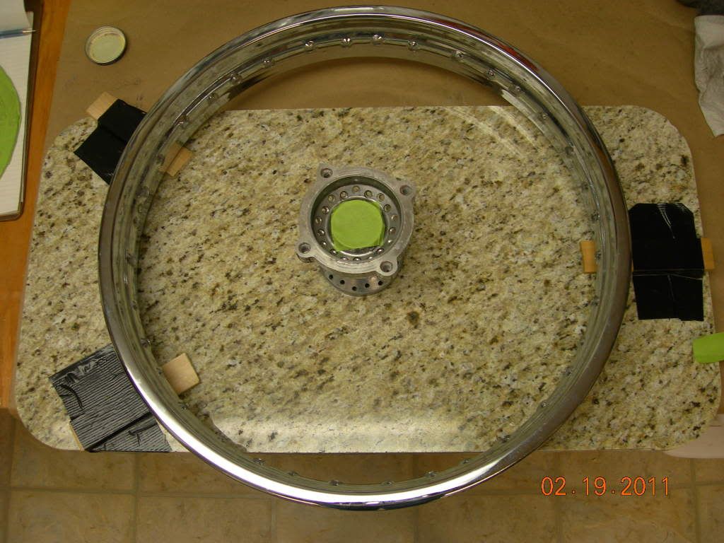
(PHOTO OF OFFSET FIXTURE)
Step 4 Rim Off Set
Notice that the rim is centered in the middle of the hub from side to side. If you set your wheel on a flat surface the rim is off that flat surface by some distance. (Note that at this point, the wheel is resting on one of the flange ends and the rim is up off of the flat surface.) Before any dis-assembly, I made a little fixture that will allow me to position the rim at that same height as it is now. When I’m ready to put the wheel back together, the fixture will make alignment easier.

As the assembled wheel is sitting on the flat surface I took three tapered wooden shims (of the type you’d find at Home Depot or a lumber yard) and slid them between the flat surface and the wheel rim.

The three shims are about equally spaced around the rim. I slid the shims toward the center of the wheel until they are touching the rim but not lifting it off the flat surface. I then taped the shims to the flat surface. I placed a mark on each shim where the rim was sitting. At reassembly I’ll put the rim back in the same place to be sure I have the correct height position. This step will make the wheel alignment easier.


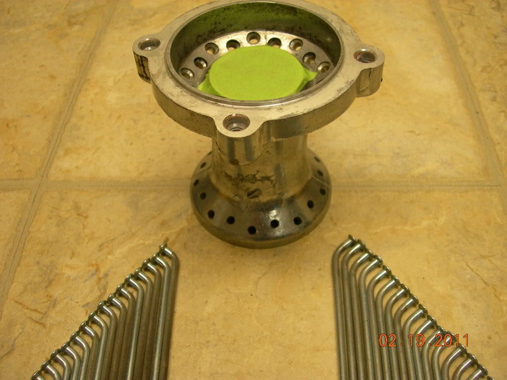
(PHOTO OF SPOKES & HUB)
Step 5 Wheel Dis-assembly
Using either the spoke wrench or adjustable wrench, remove the nipples from each spoke. It doesn’t matter where you start. I went from spoke to spoke and removed the nipples. After they were all removed from the spokes I lifted the rim out of the away and removed the spokes from the hub.

In the above picture you can see that the spokes on the left have a shorter bend than those on the right.  Also in the same picture you can see that the holes in the hub are at different distances from the edge of the flange. The spokes with the short bend (left of photo) go in the holes nearest the edge of the flange. The spokes with the long bend (right of photo) go in the holes farther away from the flange edge.


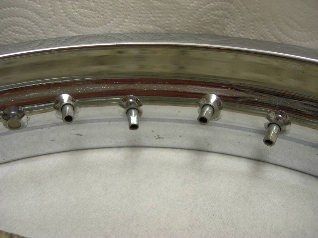
(PHOTO OF NIPPLES IN RIM)
This picture shows the angle each nipple faces in the pattern of 4 spokes. Remember this pattern will repeat 9 times around the rim.

At this point I did the hub buffing and painting. I also painted the spokes. (Here’s what I learned about painting your spokes. I used a spray can. The finish came out okay and I let the surfaces dry for several days before started reassembly. I used a lot of care in sliding the painted spokes through the holes in the hub. However I still had many nicks to touch up after assembly.)


(PHOTO OF FIXTURE, RIM & HUB)
Step 6 Lacing the Wheel
Start by gathering up the spokes and dividing them into the “short bend” and “long bend” groups. Next put all the nipples together and lubricate them with WD40 to aid assembly. Be sure to get some on the ball of the nipple where it will contact the dimple of the rim. During the alignment step, you’ll want the nipple to move freely in the dimple.

Place the rim on the fixture you made earlier with the hub in the center. You’ll be moving the rim and hub around quite a bit as you install the spokes so it isn’t too important to keep the rim right on the shim marks at this point.

Start your first 4 spoke pattern at the valve stem hole in the rim. I chose this point because it was a good visual reference point on one of my other photo’s. Be sure you have the hub positioned correctly for that first set of spokes. Refer often to your photos or sketches or my photos.

Only run the nipple about two threads onto the spoke. You’re going to need the slack to get the spokes in place.  After the first pattern is correctly installed you can continue in either direction doing one pattern at a time.
Back to top
 
« Last Edit: 04/10/11 at 15:18:06 by verslagen1 »  
  IP Logged
kernel ken
YaBB Newbies
*
Offline

SuzukiSavage.com
Rocks!

Posts: 34
Loveland Ohio
Gender: male
Suzuki wheel lacing Part two of two
Reply #1 - 04/09/11 at 09:14:56
 

(PHOTO OF PARTIALLY LACED RIM)
As you progress around the rim you’ll need to push or pull on the hub to slightly shift the location of the installed spokes. To get the last two sets of spokes in place you may have to loosen other spokes that are already in place.


(PHOTO OF FULL LACED RIM ON FIXTURE)

Step 7 Finger Tighten the Nipples
Place the wheel on the fixture and line up the rim to the marks you put on the shims earlier. Run the nipples up on the spokes finger tight.  All the nipples should have about the same number of threads showing on the spokes. The rim should be supported enough that it doesn’t rattle around but not tight because we’re going to be aligning the wheel for run-out next.

Step 8 Preparing for Run-Out alignment
To do the run-out alignment the wheel has to be free to rotate. I accomplished this by cutting a “V” notch in two pieces of wood.  I then took the front wheel axel and placed the end of it in the V notches while tightening the wood and axel in my work bench vise. I tipped the end of the axel up slightly so the wheel wouldn’t tend to come off as it was rotated. I placed the wheel on the axel and rotated it to make sure it wasn’t rubbing against anything.


(PHOTO OF DIAL INDICATOR, STAND, WHEEL & VISE)
Step 9 Radial (Fore & Aft) Run-out Measurement
I used a dial indicator to take the measurements. The stem of the indicator is riding on the inside surface of the rim. It’s important to identify your starting place on the rim. I used the valve stem hole again.

Set the indicator stem so it lightly rests on the rim. Observe the indicator as you slowly rotate the wheel for the first time. Check to ensure the indicator stem stays in contact with the rim but isn’t being forced past its travel limit.


Once you’ve established the correct setting for the dial indicator, go back to your starting point and set the dial indicator face to “zero.”


(PHOTO OF +.047 INDICATION)


Slowly rotate the wheel. Note where the high and low spots are located. I marked them with a post-it. As you start adjusting the wheel, the high and low readings will be changing. The post-its are easy to stick on and pull off. The reading, shown above, is the high spot of +.047 of an inch. That means this side of the rim is located too close to the dial indicator therefore too far away from the axle. (The rim has pushed the stem into the dial indicator causing the indicator to display a plus number above our zero starting point.) Continue slowly rotating the wheel.


(PHOTO OF -.050 INDICATION)
As I continued to rotate the rim I noticed the indicator reading started decreasing. It passed through zero and continued in a negative direction. I marked the spot where it had the largest negative number. That negative, or low spot, was -.050 of an inch. That means the rim was too far away from the dial indicator therefore this side of the rim is too close to the axle.

The two points shown in the pictures were located almost exactly across from one another. What does that tell you? What adjustments are you going to make and why? Think about it before you read on. Okay, got it?

Step 10 Radial (fore & aft) Run-out Adjustment
Let’s work with the bottom picture that shows the rim is -.050 of an inch away from the indicator (too close to the axle). To move the rim toward the indicator, thereby reducing the reading on the dial indicator toward zero, you need to loosen the spokes near the indicator and tighten the ones on the other side of the axle. That will pull the rim toward the indicator and center the wheel on the axle. Make the adjustments in small steps. Two turns on tightening on the right and two turns loosening on the left. The area of adjustment should be approximately four spokes on each side of the low (or high) point. Go slow and check around the complete wheel after each adjustment.

As you continue to make your adjustments you may find that areas you haven’t adjusted are starting to get out of round also. As you pull the rim from side to side, the spokes on the top and bottom are being pulled also. They can soon become too tight and pull the wheel out of alignment in their direction. They probably will need to be loosened a little. But, watch the dial indicator to know what to do.


(PHOTO OF WELD JOINT)
It appears the method of manufacturing of the rim is to roll-form it then weld the ends together. The weld area is then ground down. The weld area is not very smooth. When the dial indicator travels across it you will get rapid highs or lows. Just ignore this area. It isn’t something you are going to be able to adjust and it is only about an inch wide.

Keep adjusting in small steps until you have less than .040 (1 mm) run-out. It is quite possible to get the run-out down in the .015 range. That’s the goal I had set for myself, and I did get there.


(PHOTO OF SIDE TO SIDE RUN-OUT)
Step 11 Side to Side Run-out Adjustment
To do this measurement you need to reposition the dial indicator so that it is touching the outside surface of the rim, as seen in the above photo. Establish your zero point as you did before. As you slowly rotate the wheel, identify the high and low spots using post-its. (As I was doing this check I noticed one place where the reading would decrease for a very short distance then come back to its previous reading. To investigate what was occurring I used the six inch scale and placed its edge at the area where the change had been observed. I found that the rim was slightly bent there. It was over a short distance and not very deep so I ignored the reading.)

In the above photo you can see the indicator is showing a +.021 reading. That means the rim is too close to the indicator at that point. To correct that, I needed to tighten the spokes facing the far side (away from the indicator). And loosen the side near the indicator slightly.  That will pull the rim away from the indicator causing its reading to move toward zero. As before, make small changes until you get the reading you want. You should be able to align the wheel in this axis within .020 of an inch also.

After you complete the side to side alignment you need to go back and check the radial run-out once more. If necessary, keep going back and forth between the two measurements until you have the wheel aligned properly.

Step 12, The “Ping” test
The last step is to do the “ping” test. This checks the tightness of each spoke. I use a Phillips screwdriver and with the round shaft of the screwdriver, I tap each spoke. I should hear a “ping” note. If I hear a dull thud it’s a pretty sure bet that the nipple on that spoke needs to be tightened up slightly. All the spokes should yield about the same tone. A word of caution, the spokes should be snug but not as tight as you can get them. Over tightening can cause damage to the hub and spoke itself.


(PHOTO OF FINISHED WHEEL)
Okay, that’s it, you’re finished. Now, sit back, relax, enjoy the beverage of your choice and take in the beauty of the wheel you just assembled and aligned!


Back to top
 
« Last Edit: 04/10/11 at 15:21:20 by verslagen1 »  
  IP Logged
Pages: 1
Send Topic Print


« Home

 
« Home
SuzukiSavage.com
05/17/24 at 00:13:11


General CategoryTechnical Documents/Reference › Suzuki wheel lacing


SuzukiSavage.com » Powered by YaBB 2.2!
YaBB © 2000-2007. All Rights Reserved.