Here's a wiring diagram that I've successfully used on my bike:
Here's just some proof of the system working and an example of a simple way to operate the decomp:
http://static.ak.fbcdn.net/rsrc.php/z4OG5/hash/7qkbs3nb.swf?v=1250113050349&ev=0 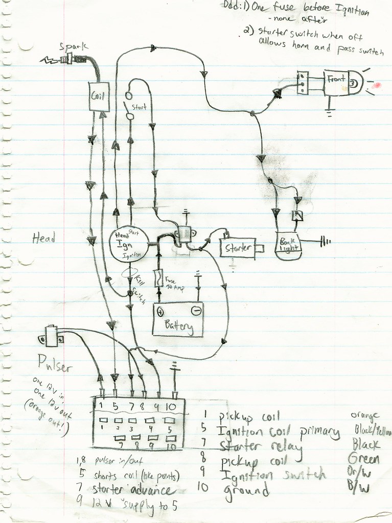 Pictures and captions of the wiring setup
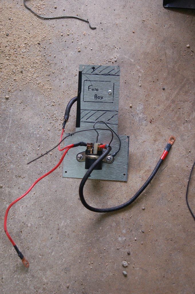
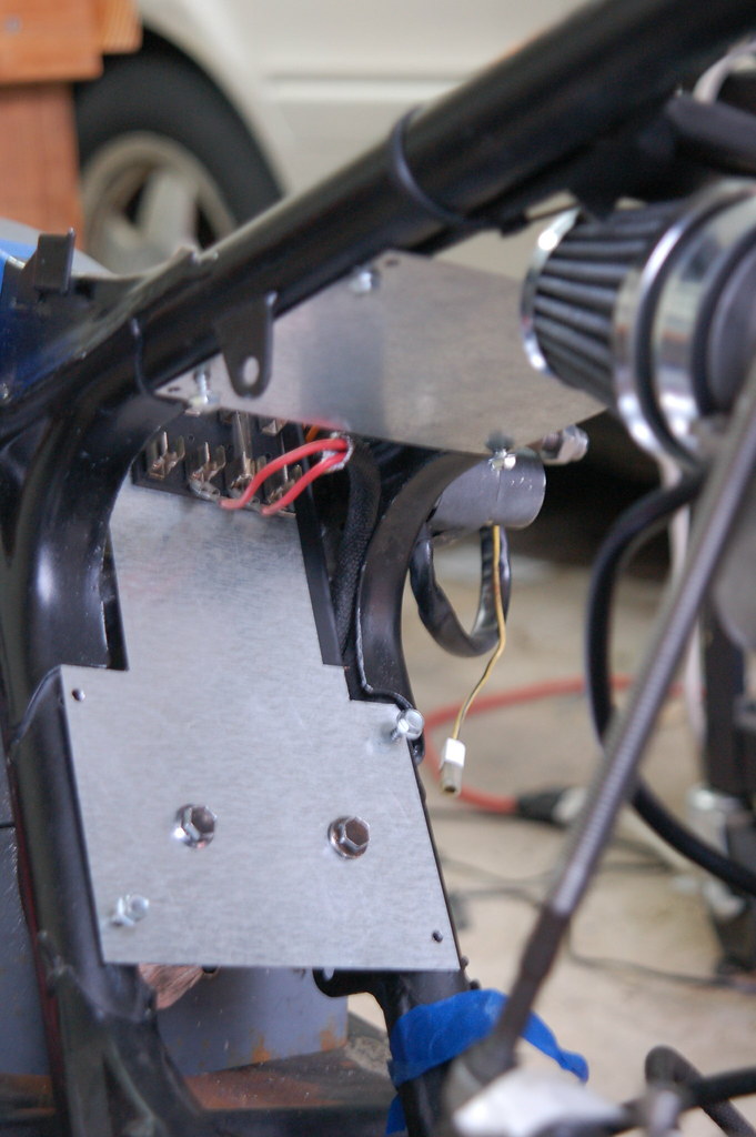
I mounted the starter relay and the fuse box on opposite sides of a plate.
The red cable on the lower left connects to the battery. The red wire on the upper left runs around the plate to the fuse box.
The exposed brass contact nub on the top left of the relay is what you connect to the starter button. Current flowing to this contact activates the starter relay.
Next to it is the plastic plug with a black wire. This is the ground of the relay activation loop.
The black sheathed cable with the red tape on the ends is the starter cable. This connects to the terminal of the starter.
Spliced with this cable is a small black wire. This connects to the electronic ignition unit. When the relay is activated, a charge is sent to the unit to change the timing of the spark.
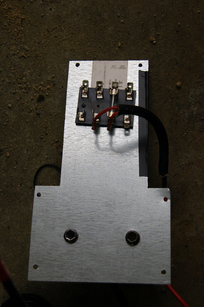
Reverse side of the plate:
Confusing jumble of wires:
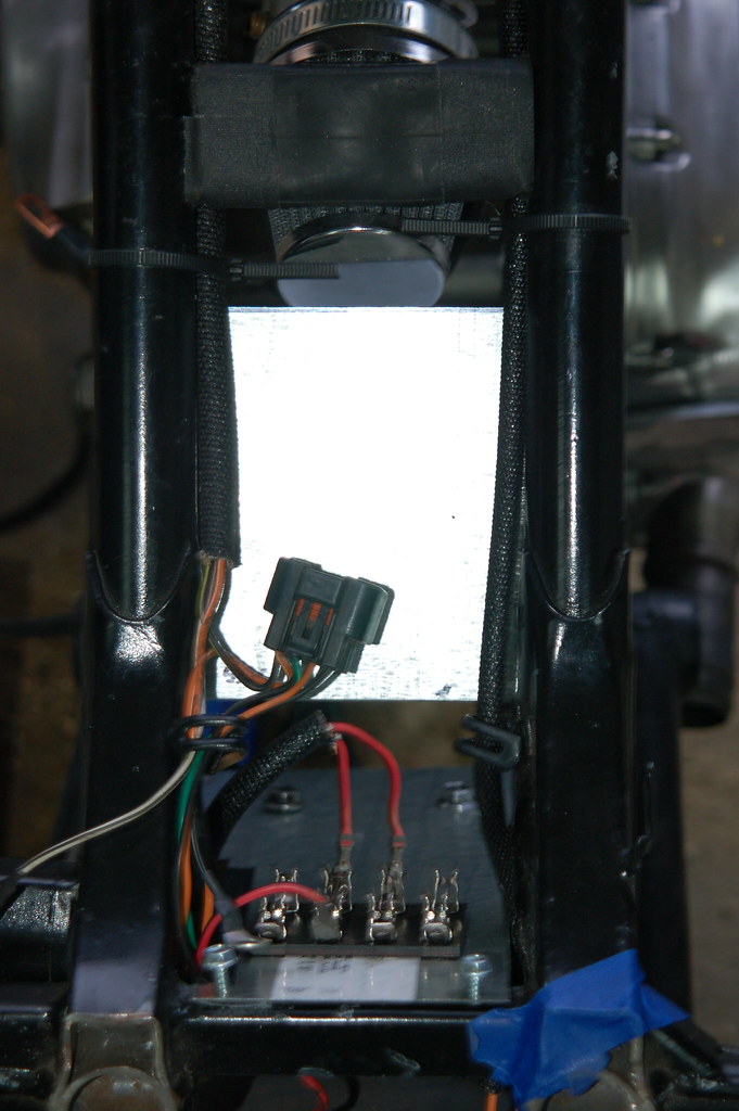
The plate mounted. It is important to make sure there is adequate metal-to-metal contact between the plate and the frame. I sanded the frame down to metal where the plate touches.

 Pages: 1

